Turret Milling Machine – Full Introduction
I. Basic Overview
Definition:
Turret milling machine, also known as rocker arm milling machine, universal milling machine, is a light-duty general-purpose metal cutting machine tool.
Functional Features:
It supports both vertical and horizontal milling, and can mill planes, inclined surfaces, grooves, splines, etc., on small and medium-sized parts. It also performs forming, drilling, cutting, profile machining, die sinking, and other operations. It features compact structure, high precision, multi-functionality, high efficiency, and easy operation.
Application Fields:
Widely used in mechanical processing, molds, instruments, meters, and other industries. Suitable for processing various precision mechanical parts such as gears, bearings, threads, and pinholes.
II. Structural Components
Bed:
The main body of the machine, used to install and connect all other parts. Composed of the bed, arbor support, base, and other components with sufficient rigidity to bear the total weight of the machine and milling forces.
Worktable:
Usually movable horizontally and vertically, used to mount and fix workpieces. Relative positions between the tool and workpiece are adjusted by moving the worktable to complete machining at different positions.
Spindle System:
The spindle is a hollow shaft with two end keys at the front for mounting tools or arbors. Tools or arbors are centered by taper fit and clamped by a drawbar through the central hole from the rear. The spindle adopts a three-support structure for high rigidity and anti-vibration performance.
Feed System:
Enables longitudinal, transverse, and vertical movement of the worktable. Driven by ball screws for high-speed, low-friction feeding. Key technical parameters include feed speed range, rapid traverse speed, motion resolution, positioning accuracy, and pitch range.
Tool Magazine:
Stores various tools required for processing. It delivers required tools to the tool change position and retrieves used tools back to the magazine per program T commands. Tool capacity generally ranges from 8 to 64 tools.
Tool System:
Includes tool station quantity, tool hole diameter, arbor size, tool change time, and repeat positioning accuracy. Tool change is usually completed within 5–20 seconds.
Cooling System:
Consists of a cooling pump, water inlet/outlet pipes, switch, and nozzles. The pump delivers coolant to the cutting area via nozzles to prevent overheating, ensuring machining accuracy and tool life.
CNC System:
An electronic display with real-time position feedback, helping operators accurately locate workpieces and perform precise cutting. It controls the entire machine motion and machining process to realize automatic production.
Electrical System:
Mainly composed of CNC device, servo system, and machine strong current control system, providing stable power supply and signal transmission.
III. Working Principle
Main Motion:
Rotational motion of the spindle, measured in r/min. Driven by the spindle motor through a transmission mechanism to provide cutting power.
Feed Motion:
Longitudinal, transverse, and vertical movement of the worktable, driven by the feed motor. It achieves precise displacement in 3D space for accurate positioning and adjustment during machining.
IV. Operating Precautions
Safety Protection:
Operators must wear safety goggles before operation. Ensure safety switches are functional. Do not touch rotating tools during machining.
Tool Installation & Removal:
Brake the spindle before changing tools. Keep taper surfaces clean, free of bumps and oil. Ensure drawbars and fixing keys are securely locked.
Worktable Adjustment:
Lock all components except those needing movement to avoid vibration. For small workpieces, adjust the worktable to a proper height and firmly clamp the workpiece.
Cutting Parameter Setting:
Set cutting speed according to workpiece hardness and tool material; set feed rate according to cutting depth and surface quality. Do not use worn tools. Use cutter heads with 4 or more inserts for face milling.
Processing Monitoring:
Concentrate during operation and do not leave the machine unattended. No wiping, adjusting, measuring, or cleaning while running. Do not stop the machine until the tool withdraws from the workpiece.
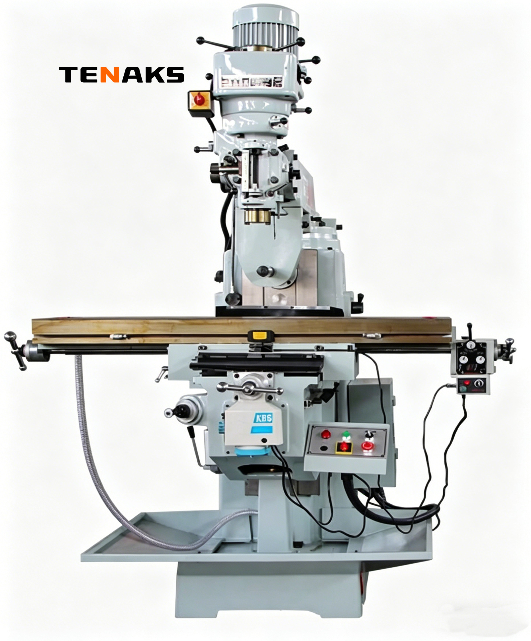
Vertical 4# Turret Milling Machine
1. Features
Multi-functionality:
Supports drilling, tapping, boring, vertical milling, etc. Capable of machining planes, grooves, inclined surfaces, formed surfaces, splines, gears, etc. Ideal for tools, molds, and fixtures.
High Precision:
Adopts Taiwanese technology and precision manufacturing. Key parts such as spindles and guideways are specially treated to ensure high dimensional accuracy and surface quality.
High Rigidity:
Base, body, worktable, and main components are made of high-strength castings with artificial aging treatment. The use of Meehanite castings enhances rigidity and stability under heavy cutting loads.
Excellent Flexibility:
The milling head can tilt ±45° vertically and rotate 360° horizontally. The worktable moves along X, Y, Z axes, enabling various angle adjustments for complex-shaped parts.
Easy Operation:
The control system is suspended on the upper right, ergonomically designed. The control panel uses intuitive symbols for simple and clear operation.
2. Technical Parameters
Worktable:
Table size: approx. 1270×254mm Longitudinal (X-axis) travel: 780–850mm Transverse (Y-axis) travel: 380–420mm Vertical (Z-axis) travel: 350–380mm
Spindle:
Spindle taper: typically R8; optional ISO-30, ISO-40 Spindle speed range: 66–4540 r/min
Motor Power:
Main motor: 2.2KW / 3HP Lifting motor: 1.1KW
T-slots:
Width: 16mm, number: 3 slots
3. Operating Precautions
Pre-operation Preparation:
Check machine conditions, lubrication, and handle positions. Select proper tools and fixtures, install tools correctly, and clamp workpieces firmly.
Parameter Setting:
Set spindle speed, feed rate, cutting depth reasonably according to material and tool types. Do not exceed rated parameters.
Processing Monitoring:
Closely observe cutting status, workpiece clamping, machine sound, and vibration. Stop immediately for inspection if any abnormality occurs.
Safety Protection:
Wear safety goggles to prevent chip injuries. Do not touch tools or workpieces during operation.
Post-processing Maintenance:
Turn off power, clean chips and debris. Perform lubrication and guideway maintenance to extend service life.